Ask von Neumann About Computer Assembly
In the previous post, we defined computers as programmable machines and explored the idea of separating hardware and software through the Turing machine. While Turing provided the theoretical foundation for computing machines, an important question remained: How could such a machine be implemented in the real world?
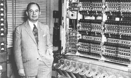
This is where John von Neumann entered the scene—an American computer scientist, mathematician, scientist, and economist. The von Neumann architecture he proposed in 1945 is the basic design principle followed by almost all computers today, from your smartphone to supercomputers.
In this article, we’ll explore von Neumann’s core ideas and see the big picture of how the logic gates we created earlier become part of massive systems like CPUs and memory. Let’s see how an idea from 80 years ago became the foundation of modern computers.
Rewiring Thousands of Cables…?
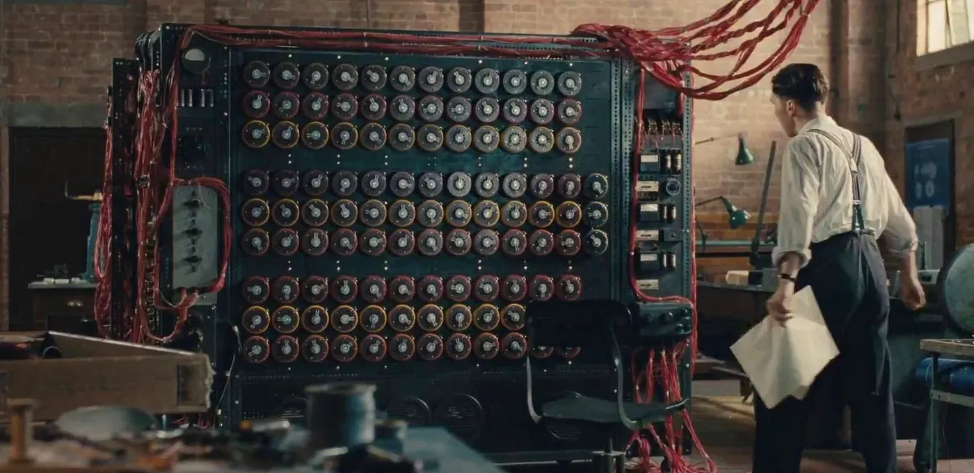
Early computers before the von Neumann architecture operated in a highly inefficient manner. Consider this historical account:
One of the peculiarities that distinguished ENIAC from all later computers was the way in which instructions were set up on the machine. It was similar to the plugboards of small punched-card machines, but here we had about 40 plugboards, each several feet in size. A number of wires had to be plugged for each single instruction of a problem, thousands Of them each time a problem was to begin a run; and this took several days to do and many more days to check out.
Franz L. Alt, “Archaeology of Computers—Reminiscences, 1945–1947,” Communications of the ACM, Vol. 15, No. 7, July 1972, p. 694.
For ENIAC, a program was literally the physical structure of the machine itself. This was like having to rebuild your entire kitchen every time you wanted to cook a different dish.
Von Neumann Architecture
Von Neumann solved this problem by redefining the very concept of a program. Instead of viewing programs as the physical wiring state of hardware, he treated them as data. This is like keeping your kitchen unchanged and simply referring to a new recipe when cooking something different.
This idea is the core of the von Neumann architecture: the Stored-Program Computer. Without touching any wires, the computer could perform completely different tasks simply by loading a new program stored in memory.
But what exactly does “programs are data” mean? To understand this, we need to examine what machine language—the language computers understand—looks like.
Machine Language
As we saw in the first article, computers represent all information using only 0s and 1s, and programs are no exception. Machine language, the language computers understand, consists entirely of combinations of 0s and 1s. For example, if we want to tell a computer to “add two numbers,” we need to translate this into binary numbers like 00110000.
The important point here is that there’s no magic in 00110000 meaning addition. It’s simply an agreement between the person designing the CPU and the person writing the program. It’s a predetermined rule: “When you see an instruction starting with 0011, activate the addition circuit.”
Real computer machine language is quite complex, but to understand the core principles of the von Neumann architecture, I’ve created a very simple 8-bit machine language for this article. Click on each instruction in the instruction set viewer below to see its structure and description. Don’t worry about unfamiliar terms like registers or Z flags—we’ll cover them soon. For now, just understand how 0s and 1s can be interpreted this way.
Instruction Structure
Example
MOVE R1, R2  // R1 = R2
00000110
Wait, you might ask—if programs consist of 0s and 1s, what are those human-readable words like MOVE and ADD? Since it’s difficult for programmers to memorize binary numbers like 0001, each instruction is given a mnemonic (a memory-aid abbreviation).
Ultimately, machine language is a collection of simple agreements, though it may look complex. Rules like “When you see this number combination, perform addition” or “When you see that number combination, move data.” This collection of agreements is called the Instruction Set Architecture (ISA) in computer terminology.
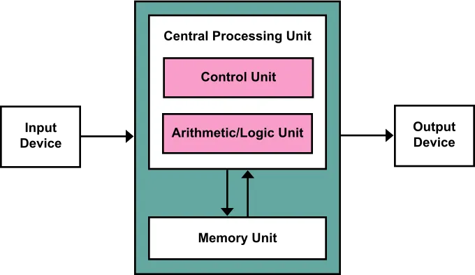
Now that we’ve examined machine language, let’s look at what components make up a von Neumann architecture computer that executes this machine language. It’s broadly divided into memory, CPU, and input/output devices.
Memory
Memory stores all the information a computer needs to work. The key characteristic here is that each storage location has a numeric address. For example, you can give commands like “fetch the data at address 100” or “store 50 at address 2048,” and the memory will immediately find or store data at that location.
Try reading and writing data through addresses in the memory simulator below. Remember that in reality, you can’t see the memory contents like the table below—you can only read and write values accessed by address:
CPU
The CPU sequentially fetches programs stored in memory, interprets them, performs necessary calculations, and controls other parts of the computer to move. True to its name as the Central Processing Unit!
The CPU is broadly divided into registers, ALU, and control unit. Let’s examine them in order.
Registers
If memory is the computer’s large warehouse, registers are small workbenches inside the CPU. While memory has large capacity but relatively slow access speed, registers have very small capacity but can be accessed at ultra-high speed.
What would happen without registers? The CPU would have to fetch data from memory every time it performs operations, and all intermediate results would have to be stored in memory. This would be like going to the warehouse to fetch ingredients one by one every time you cook—very inefficient.
Among registers, one is particularly important: the Program Counter (PC). The PC is a register that stores the memory address of the currently executing instruction, like a finger pointing to which step of a recipe you’re currently on.
For example, if the PC points to address 100, the CPU fetches the instruction from memory address 100 and executes it. After instruction execution, the PC typically increments to the next address to prepare for the next instruction. This process repeats as the program executes sequentially. Of course, when encountering instructions like JUMP, the PC can jump to a specified address to change the program’s execution flow.
ALU
Following the control unit’s instructions, it performs actual operations using register values. It handles not only arithmetic operations like addition and subtraction, but also logical operations like AND, OR, and NOT that determine “true/false.” Remember when we combined logic gates (AND, OR, NOT) to create an adder in the early series? That circuit, in a more sophisticated form, constitutes this ALU.
The ALU provides additional information called flags along with operation results. For example, the Zero Flag (Z) indicates whether the operation result is zero or not. An operation like 5 - 5 = 0 sets the Z flag to 1 (true), while an operation like 3 + 2 = 5 sets the Z flag to 0 (false). Such flags are used in subsequent conditional statements to make decisions like “if the result is zero, jump to different code.”
Control Unit
It fetches instructions from memory, decodes them, and sends appropriate signals to other parts of the computer to direct their work. Check out what instructions each command gives in the control unit simulator below.
MOVE Rd, Rs
Copies the value from register Rs to register Rd.
Input/Output Devices
Input/output devices are the CPU’s windows to communicate with the world. All processes of receiving text input from keyboards, reading coordinates from mice, and displaying results on monitors fall under this category.
One interesting way to implement input/output devices is to utilize memory. This is like designating a specific drawer in an office as a “communication box with the outside world.” Specific memory address regions are pre-arranged with input/output devices, and the CPU simply controls devices by reading or writing values to those addresses.
For example, you can map a specific memory region one-to-one with monitor screen pixels. When the CPU writes a value of 1 (black) to that memory address, the corresponding monitor pixel turns black, and when it writes 0 (white), it turns white. Keyboards can also work by continuously writing the code of the last pressed key to a specific memory address. The CPU just needs to periodically read that memory to receive key input.
Below is a simulator that mimics a 10x10 monitor and its connected video memory (VRAM). Try directly changing memory values and observe how the screen changes.
Screen (10x10)
Video Memory (VRAM)
* Modify the 0s and 1s in the text area.
Putting It All Together
Great! Now we’ve examined all the core components of the von Neumann architecture. We understand how memory, CPU, and input/output devices work individually, but we haven’t yet seen how they actually cooperate to execute programs. Now let’s see the process of assembling these components into a complete computer.
Try writing and executing programs in the simulator below. Observe the process of fetching programs stored in memory one by one, interpreting them, and making the computer move accordingly.
CPU State
Conclusion
In this session, we explored how the Turing machine was implemented in reality through the von Neumann architecture. By treating programs as data stored in memory rather than hardware wiring, it became possible to perform various tasks with software alone without hardware changes.
We also examined the core components of the von Neumann architecture: memory that stores programs and data based on addresses, CPU consisting of a control unit that interprets instructions, ALU that performs operations, and registers as temporary storage, and input/output devices that connect users with computers.
But one important question remains: How exactly are machine language instructions like 10110000 stored in memory actually processed in the CPU? We said the control unit “interprets” instructions, but what specific steps does this involve, when do the ALU and registers intervene, and when and where do the results go?
In the next article, we’ll solve this curiosity by examining the Fetch-Decode-Execute-Write Back cycle, the basic working cycle of CPUs. By following the entire process of how a single instruction is processed step by step, we’ll directly observe this cycle that repeats billions of times per second inside computers even as you read this article right now.
You need to login to leave a comment.